New StruBIM Suite programs
IFC BUILDER
Creation and maintenance of building IFC models. This application is integrated in the OPEN BIM workflow via the IFC4 standard.
Features:
- Graphic user interface (GUI) to introduce columns and flat slabs
- Import of DXF/DWG/JPG/BMP files
- Open BIM edges generation
- Open BIM (IFC4) modelling
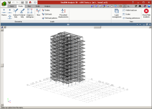

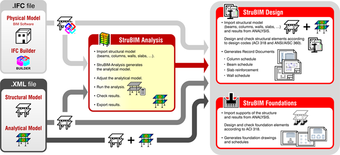
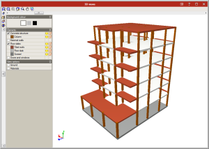
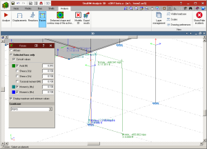
StruBIM Analysis 3D
StruBIM Analysis 3D is a tool created to generate, edit and design an analysis model that has been developed based on a structural model.
The analysis of the acting loads is carried out using a 3D spatial analysis applying stiffness matrix methods.
The structural model can be imported using an IFC format file, generated using CYPE’s IFC Builder, other BIM modelling programs or an XML format file.
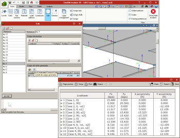
The analysis model is generated based on the imported structural model, and the structure is discretised into bar-type elements, nodes and shells composed of finite elements (FEM). Users can adjust the model by defining or editing:
- Loadcases
- Values of loads acting on elements.
- Wind loads that are generated automatically in accordance with ASCE 7-10
- Diaphragms
- Boundary conditions
- Section and material properties
- Shell discretisation sizes
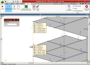
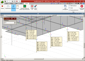
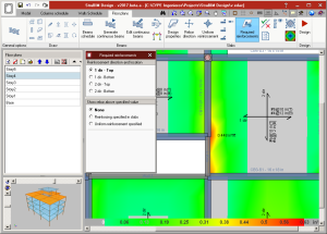
Once the analysis has been completed, users can consult:
- Displacements and reactions
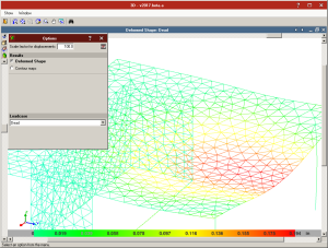
- Force and displacement diagrams
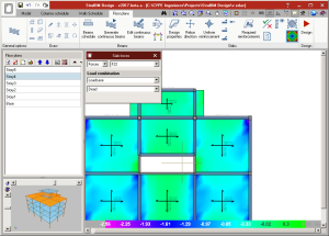
- Contour maps for forces and displacements
The analysis model and its results are exported to StruBIM Design.
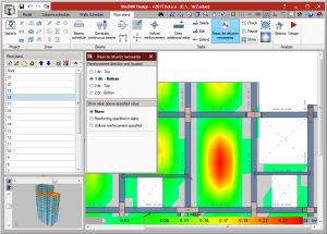
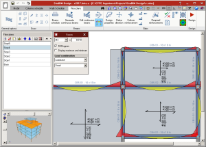
StruBIM Design
StruBIM Design is a tool which designs, checks and edits reinforced concrete and steel structural elements, based on a structural model and a calculated analysis model.
The structural model can be imported using an IFC format file that has been generated using CYPE’s IFC Builder, other BIM modelling programs or an XML format file. The calculated analysis model is imported from StruBIM Analysis 3D or from the XML file if it contains the necessary information.
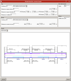
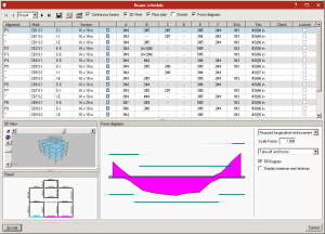
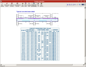
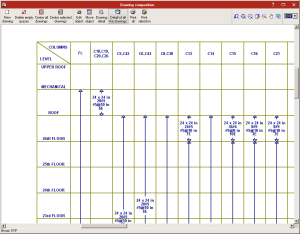
StruBIM Design designs and checks s tructural elements (columns, beams, floor slabs and walls) and provides the technical drawings in accordance with the requirements of the project (Record Engineer).
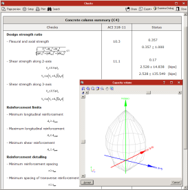
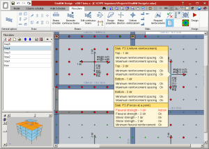
The reinforcement of the following reinforced concrete elements is designed and checked in accordance with the requirements of ACI 318-14, ACI 318-11 and ACI 318-08:
- Rectangular or circular-section columns
- Rectangular-section beams
- Flat slabs
- Walls
Steel elements are designed and checked in accordance with ANSI/AISC 360-10.
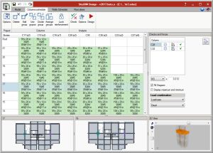
Design results for reinforced concrete elements (sections and reinforcement) and steel elements (sections) can be edited, and then checked.
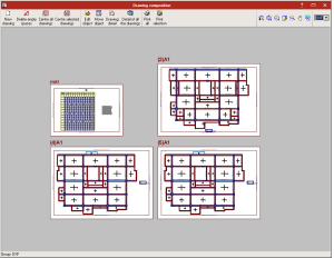
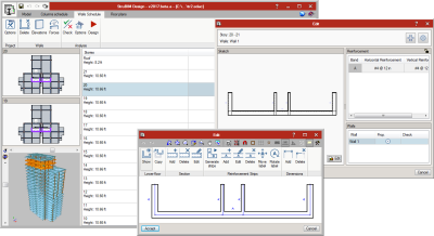
Design results can be directly transferred to technical drawings of the various elements: columns, beams, slabs and walls, in accordance with representation requirements and project contents (Record Engineer):
- Column schedule
- Beam schedule
- Slab reinforcement drawings
- Wall schedule
Versions
Three program versions of StruBIM Analysis 3D and StruBIM Design are available:
- StruBIM Free
- StruBIM Pro
- StruBIM Expert
The features of each version can be consulted at Features of StruBIM versions webpage.
More information on StruBIM Suite
More information on StruBIM Suite can be found on his webpage.
Open BIM workflow: Consolidation
The group of programs integrated in the Open BIM workflow carried out the export and import of geometrical models in IFC4 format.
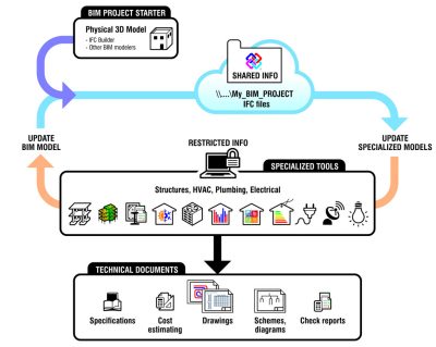
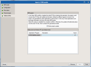
As of this version, as well as importing and exporting geometrical models in IFC4 format, the information regarding the analysis and design of building services, obtained using specialized programs (design programs) of CYPETHERM Suite, is also exported and imported. This way the BIM model of the project is updated and the Open BIM workflow is closed.
CYPETHERM Suite design programs allow users to automatically generate a new project by importing a BIM file with geometric information (BIM Project Starter). Now, additional IFC files containing useful information, and generated by the remaining specialized programs of CYPETHERM Suite, can be imported when the project is created or at any other stage (Update Specialized Models). As users do not only work with one IFC file containing geometric information but with a group of files containing the geometric, analysis and design information of a project, each BIM project must be generated in an independent directory to have all the information in a single location, and for the programs to only read the corresponding IFC files.
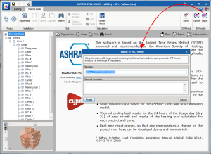
One of the many benefits of Open BIM workflow can be seen, for example with CYPETHERM LOADS and CYPETHERM HVAC.
Users can export from CYPETHERM LOADS, once the project has been analysed, all the information regarding the thermal loads of the precincts, in IFC format using the “Export” option.
CYPETHERM HVAC requires the thermal load information of the building to be able to carry out the analysis and design of air conditioning systems. This information can be introduced by users or can be imported from the BIM project, if the data has been exported from CYPETHERM LOADS.
CYPELUX
Lighting of work places
As of 2016.j version, CYPELUX performs the analysis of the parameters which define the lighting quality and comfort established in the EN 12464-1:2011 code (Lighting. Lighting of work places. Part 1: Indoor work places).
For CYPELUX to be able to carry out this analysis in accordance with EN 12464-1:2011, the user license must include the "Interior lighting check in accordance with EN 12464-1" module.
More information on CYPELUX can be found on his webpage.
Arquimedes
Bill of quantities of Revit models
Comments composition for the quantities table
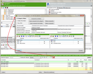
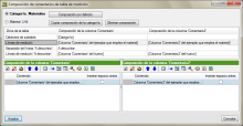
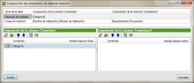
The Comments composition for the quantities table dialogue box, which appears when the Comments button  is pressed, has been improved. Users have more comment construction possibilities for Subtable headers, Quantity lines, Line spacers “To deduct” and Quantity lines “To deduct”. The composition of the Comment and Comment2 columns can be seen in a single dialogue box, allowing users to compare both comments at the same time.
Default compositions are created using information of the Category, Family or Type of the quantity elements, which aids in composing the comments.
When quantities are extracted, if comments have been defined using the Category, Family and Type information (or any combination of them), the comments that have been created using the more detailed information prevail. The priority is Type > Family > Category. In other words, the program checks to see if there are any comments in Type and if so, these comments are used. If none are found, the program checks if there are comments present in Family, otherwise it checks if there are comments in Category.
If the quantities of the job item are obtained by linking them to a Material, as of the 2016.j version, comments can be composed by using information of the Material category or of the material itself.
If job items are assigned from the Rooms tab, the creation of the comments is simplified.
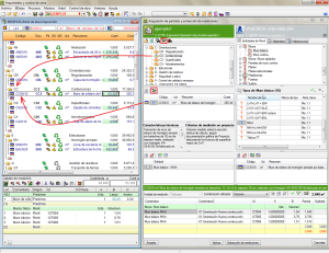
Show chapter or job item in the “Decomposition tree” window
A new button Show in the “Decomposition tree” window  has been added in the Job item assignment and quantity extraction dialogue box (which appears when a Revit job is linked to Arquimedes). This button displays the chapter or job item that has been selected from the chapter or job item zone of the “Job item assignment and quantity extraction” dialogue box, whilst the position of the current column is maintained in the Decomposition tree window.
As an example, using this option, users can obtain a parallel view of the status of the (already consolidated) quantities contained in the Decomposition tree window and those to be extracted in the “Job assignment and quantity extraction” dialogue box.
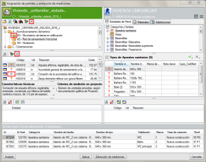
Mark chapters or job items that are not to be measured
In order to aid users to identify chapters and job items that are not going to be measured using the Revit model, the button has been added in the chapter and job item zones of the Job item assignment and quantity extraction dialogue box.
To mark chapters or job items which are not to be measured, the button corresponding to chapters or job items must be pressed. In no case does the mark prevent or block the program from carrying out the measurement. Upon pressing the button, the mark to not measure can be added or removed.
Return to the 2016 version download area
Tel. USA (+1) 202 569 8902 // UK (+44) 20 3608 1448 // Spain (+34) 965 922 550 - Fax (+34) 965 124 950