
![]()
- Code implementation and improvements in its application
- Open BIM technology in CYPE programs
- CYPECAD
- CYPELUX
- CYPESOUND
- CYPETHERM HVAC
- Arquimedes
- Return to the 2017 version download area
Code implementation and improvements in its application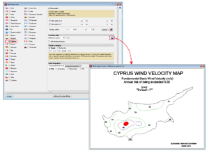
Loads on structures. Wind loads
CYS EN 1991-1-4:2005 (Eurocode 1 – Cyprus)
National Annex to CYS EN 1991-1-4:2005. Eurocode 1: Actions. Part 1-4: General actions – Wind actions.
Implemented in CYPECAD.
Loads on structures. Seismic loads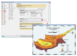
CYS EN 1998-1:2004 (Eurocode 8 – Cyprus)
Since previous versions, users could maintain the link to the original BIM model after importing it in the program. If the link was not kept, the selected import was carried out but its 3D geometry could not be visualised.
As of the 2017.c version, a third option is available which allows users to also import the 3D Geometry and precincts, without having to keep the model link.
Open BIM technology in CYPE programs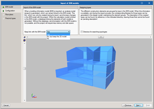
Links with the BIM model
Since previous versions, users could maintain the link to the original BIM model after importing it in the program. If the link was not kept, the selected import was carried out but its 3D geometry could not be visualised.
As of the 2017.c version, a third option is available which allows users to also import the 3D Geometry and precincts, without having to keep the model link.
CYPECAD
Integration of CYPECAD in the Open BIM workflow

Introduction
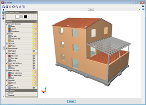
As of the 2017.c version, CYPECAD becomes part of the group of programs that are integrated in the CYPE Open BIM workflow. Projects can be created and linked to a BIM project by means of IFC files which store the information of the architectonic model of the building.
CYPECAD is integrated in the proposed workflow by using the architectonic model as an updatable template to introduce the structural model, analyse and design it.
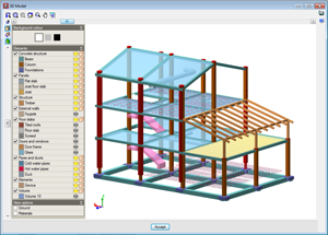
When a projected is linked, all the IFC files that are present in the BIM project directory are read. The structural model created in CYPECAD can be viewed in the 3D view of the BIM model, as well as the consolidated BIM model (all the IFC files making up the BIM project: HVAC installations, radiating floor circuits,...).
The structural model that is introduced in CYPECAD can be exported in IFC format to complement the BIM model. Once it has been exported, the other applications that are integrated in the workflow can update the BIM model and view the structural model of the building (consolidation of the BIM model).
Projects linked to a BIM model
In the 2017.c version of CYPECAD, the following elements of the architectonic model are imported and updated to easily introduce the structural model:
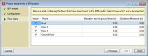
- Floors
In the CYPECAD model, each floor is linked to the equivalent floor of the architectonic model. Nonetheless, elevation differences can be defined with respect to the elevation of the floor, for example, to deduct the thickness of the non-structural flooring. Floor modifications in the BIM model, such as elevation changes, creation of new floors or deletion of existing floors, can be updated automatically. - Columns
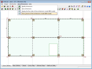
The outlines of the columns that have been defined in the architectonic model can be seen in the Column Definition tab. When columns are introduced, the outlines of these architectonic columns are snapped to and a fixed point is proposed. When a column is introduced on an outline that is not present on all the floors of the BIM model, the program proposes it be placed only on the floors where it is present. - Floor slab outlines of the architectonic model
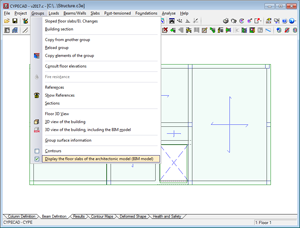
The floor slab outlines defined in the architectonic model can be represented in the Column Definition and Beam Definition tabs. The outlines can be activated or deactivated using the menu option: Groups > Display the floor slabs of the architectonic model (BIM model). The outlines work as a drawing template to introduce beams more easily.
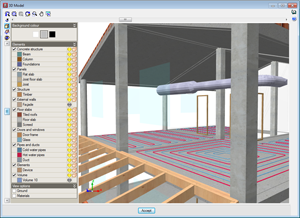
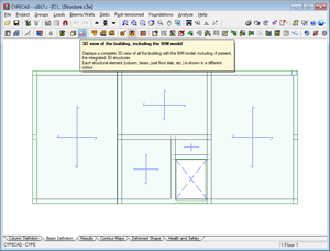
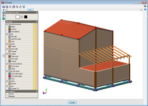
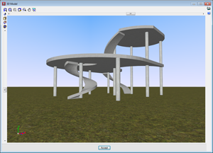
- 3D view of the BIM model
As well as the 3D view of the structure, the option to see the 3D view of the BIM model has been added. The view can be accessed by clicking on the icon from the toolbar or from the Groups menu.

Updating the BIM model 
To update the BIM model, the IFC files contained in the directory of the BIM project have to be read. Any changes that have been carried out on the architectonic model can update elements of the analysis model of CYPECAD (floors, floor slab outlines and column outlines). The additional IFC files update the 3D view of the BIM model.
The updating process carried out in CYPECAD due to modifications that have been carried out in the architectonic model, can be configured by activating or deactivating the following actions:
- New elements
- Include new elements of the BIM model in the analysis model: New floors or new column or floor slab outlines are added.
- Modified elements
- Update the elements of the design model that have been modified in the BIM model
- Update the analysis elements even if they have been modified
- Recover elements deleted in the analysis model
- Deleted elements
- Delete the elements of the analysis model that have been deleted in the BIM model
- Delete the elements of the analysis model even if they have been modified
Export in IFC format 
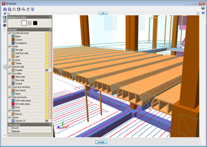
The structural model defined in CYPECAD can be exported in IFC format to the directory of the BIM model. The different elements making up the structure are exported: columns, beams, joists, forms, footings, pile caps, flat slabs, waffle slab forms, post-tensioned tendons, integrated 3D structures, stairs...
Assign steel and timber joists
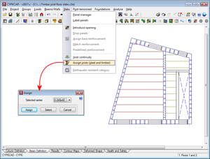
As of the 2017.c version of CYPECAD, before launching the analysis, a section of the series used to define the steel or timber joist floor slabs can be assigned to the panel. This way, when the first analysis of the structure is launched, the stiffness of the section used in the analysis is that of the assigned section and not the stiffness of the smallest section of the series.
To do so, the option: “Assign joists (steel and timber)” has been implemented (“Beam definition” tab > “Slabs” menu).
It is also possible to assign the section when a floor slab is introduced or edited. To do so the option: “Initial section”, has been implemented in the new and editing joist floor slabs menus for steel and timber joists.
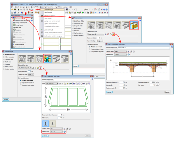
Once the project has been analysed, the section that is obtained in the design process will be the one assigned to the floor slab and therefore, its stiffness will be the one contemplated if a new analysis of the structure is launched.
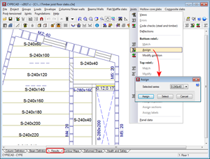
Users must bear in mind that when the structure has been analysed, and as long as no modifications are carried out which eliminate the design results, the “Assign joists (steel and timber)” option will not be active in the “Slabs” menu in the “Column definition” tab. In this case, joists can be assigned in the “Results” tab using the “Assign” option in the “Joists” menu, where users can also check the results if the section of the joist is changed.
Caissons
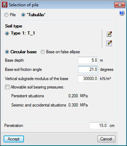
As of the 2017.c version, users can introduce, check and design caissons for the following concrete codes:
- CIRSOC 201-2005 (Argentina)
- ACI 318M-08 (USA)
- ACI 318M-11 (USA)
- NCh 430 Of 2008. D° 60:2011 (Chile)
- NTCRC:2004 (Mexico)
- NSR-10 (Colombia)
- NTE E.060:2009 (Peru)
As of previous versions, users could already introduce, check and design caissons (Tubulões) for the following Brazilian concrete codes:
- ABNT NBR 6118:2007
- ABNT NBR 6118:2014
When caissons are designed in CYPECAD with the Brazilian design codes, the quantities exported to Arquimedes include those of the “Tubulões”.
The program displays on-screen and provides reports of the checks that have been carried out for the aforementioned codes.
Earthquake resistance category of floor slabs
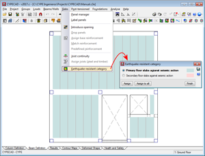
As of the 2017.a version, CYPECAD allows users to assign an earthquake resistance category to concrete beams (primary or secondary), in such a way that those selected as being secondary beams are not considered as being part of the structural system that has to resist seismic action. The stiffness of these beams is reduced in the analysis and the checks carried out on them are different compared to those carried out on beams considered to be primary beams. More information can be found in the section: “Earthquake resistance category” in the new features of the 2017.a version.
As of the 2017.c version, the earthquake resistance category of floor slabs is implemented, which allows users to class the following types of concrete floor slabs as primary or secondary:
- Flat slabs (reinforced and post-tensioned)
- Waffle slabs
- Hollow core slabs
- Concrete joist floor slabs (generic, precast reinforced, prestressed reinforced, or in situ joists)
In the “Earthquake resistant category” dialogue box (“Beam definition” tab > “Slabs” menu > “Earthquake resistant category”), users can assign this category to concrete slabs. By default, any slab that is introduced has assigned the “Primary slab against seismic action” category.
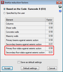
Just as for concrete beams, concrete floor slabs which are assigned as being secondary are not considered to be part of the earthquake-resistant structural system. To do so, CYPECAD reduces the stiffness in the analysis of these elements in a ratio, that can be edited, which by default is 0.01. Users have two options to indicate the inertia reduction factors that are to be used in the analysis. These are located in the “Inertia reduction factors” dialogue box (“Beam definition tab” > “Project” > “General options” > “Inertia reduction factors”) and are “Based on the code” (default option) and “Specified by the user”.
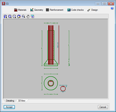
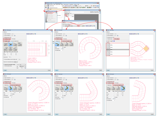
Curved staircases
Users can now introduce curved flights of stairs using the “Stairs” module of CYPECAD. The “Predefined shape” option includes:
- Straight flights
These are the predefined types included as of previous versions.
- Curved and straight flights
- Curve
- Curve with straight flight
- Curve with two straight flights
- Two curves with three straight flights
Using the “Free shape” option, users can combine straight and curved flights, and create an infinite number of staircase shapes.
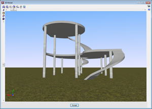
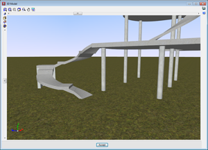
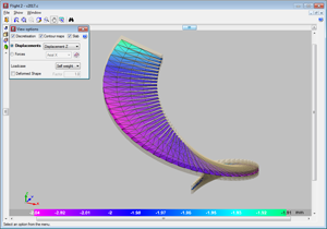
The finite element analysis model for staircases operates, as it always has, independently from the rest of the structure for the analysis. The program automatically transfers the loads of the stairs to the complete structural model at its supports, start, end and intermediate supports as averaged line loads.
Transposed steel columns
An option has been implemented in CYPECAD whereby users can rotate the section of a selected steel column by 90° about its centre of mass, during the introduction or editing process. This operation does not take into account the fixed position of the column. A column marked “T” appears next to the selected section type, which when marked “transposes” the position of the column in the indicated span.
The operation carried out to transpose a column does not usually provide the same results as applying a rotation of 90°. A 90° rotation is applied to all the spans (floors) of the columns and about the selected fixed point. By transposing the column section, however, the column rotates 90° about the centre of gravity of the section and only the selected column spans rotate. Therefore, the choice as to which option to use will depend on what users wish to do.
CYPELUX
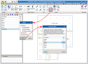
Copy elements from one floor to another
With the 2017.c version, users can copy elements from one floor plan to another using a new button located in the Edit menu of the toolbar. Users must choose which CYPELUX entities are to be duplicated (amongst the options available are the lights which make up the lighting installation and safety/protection elements, such as evacuation routes and equipment) to then choose on which floor they must be duplicated.
This tool, which has already been implemented in other programs, such as CYPETHERM HVAC, is of great importance when trying to reproduce the same distribution on different floors of a BIM model, where floor plans are defined by the geometry of the IFC.
CYPESOUND
Import the noise produced by the openings of ventilation systems
Users can import the noise produced by the end elements of the ducts of the HVAC system installed in the building. Thanks to CYPESOUND being an application that is integrated in the Open BIM workflow, this operation can be carried out using IFC information exchange files. To do so, the acoustic parameters must first be exported to IFC using software that also operated with this technology, such as CYPETHERM HVAC, CYPE’s heating, ventilation and air conditioning program.
Once the integration process has been finished, users will have the option to edit the data that has been introduced automatically and indicate the remaining properties that define the noise that is generated by the air conditioning installation.
CYPETHERM HVAC
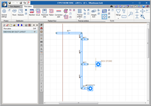
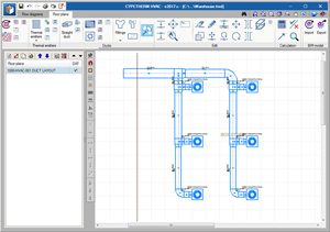
Automatic generation of duct connections
As of the 2017.c version, CYPETHERM HVAC automatically generates all the connection elements of the network: elbows, transitions and branches.
Therefore, as of this version, the introduction and design procedure of a network is as follows:
- Introduce ducts
- Introduce grilles or diffusers
- Design ducts
- Automatically generate connections

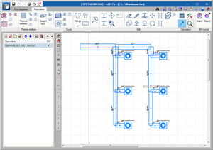
Positioning of grilles in ducts
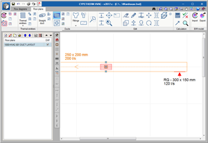
In previous versions, a grille was introduced by pressing the mouse button at the position where it was to be placed in the duct.
As of the 2017.c version, the position of a grille in a duct requires to clicks of the mouse button. The first click marks the position of the grille along the duct and the second defines whether it is to be placed vertically or horizontally. To define which of the three positions will be that adopted by the grille (horizontal, vertical, to one side or the other of the duct), before pressing the mouse button for the second time, users can move the mouse cursor to one side, the middle or the other side of the selected duct. An image appears on screen, upon moving the cursor, indicating which will be the position of the grille if the mouse is clicked on for a second time.
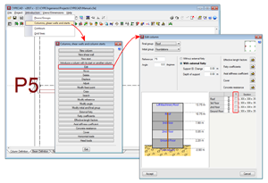
Fan coils. Design and selection
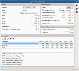
As of the 2017.c version, and as occurs with other elements, each fan coil that is incorporated in the drawing has a properties panel where users can indicate the type of fan coil, the loads to cover, the working temperatures, ventilation flow, etc. The program calculates the corrected load depending on the ventilation air conditions, and checks if the selected fan coil model has enough power to cover these loads.
The fan coil library, which is available in the General settings of the program, displays the nominal power of each model, air flow of the ventilator, etc.
Arquimedes
View details lines in quantity, study, sale and execution tables
As of the 2017.c version, users can carry out a specific configuration of the view of the details of the quantities, which complements and simplifies the view of the quantity tables resulting from the quantity extraction of Revit. This is possible by pressing the column header ![]() of the quantity, study, sale, execution or certification details tables.
of the quantity, study, sale, execution or certification details tables.
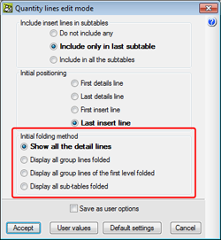
The view configuration of the quantity details lines can be configured in accordance with the following options:
- Show all details lines
- Display all group lines folded
- Display all group lines of the first level folded
- Display all sub-tables folded
When quantities do not come from Revit, there are no groups (quantity line groups) but, if there are sub-tables in the tables, these behave as groups.
In the “Quantity lines editing mode” dialogue box (Show > Configuration> Quantity lines edit mode), a new section has been added “Initial folding method” which also includes the four options indicated above, so the default folding method for the quantity lines can be selected.
Bill of quantities of Revit models
Group quantity details lines coming from Revit
To simplify the number of details lines that are displayed in the quantity tables when quantities are extracted from the “Job item assignment and quantity extraction” dialogue box, a system has been created to group and view quantity lines, which also affects templates and quantity reports.
Grouping of the quantities lines is done after assigning job items the corresponding Types to the Revit elements.
The grouping action is carried out by creating or editing (![]() or
or ![]() buttons) a usage combination to extract the quantities. In the dialogue box that opens (selection of parameters to obtain the quantities), the dimensions which coincide can be grouped or accumulated in columns A, B, C, D, or E by activating respectively, the values of the Group and Accumulate columns. This operation can be carried out in the “Element measurements” tab or in the “To discount” tab.
buttons) a usage combination to extract the quantities. In the dialogue box that opens (selection of parameters to obtain the quantities), the dimensions which coincide can be grouped or accumulated in columns A, B, C, D, or E by activating respectively, the values of the Group and Accumulate columns. This operation can be carried out in the “Element measurements” tab or in the “To discount” tab.
Quantity groups in quantity tables coming from Revit
Quantity groups in quantity tables from Revit are obtained based on a classification and organisation process depending on the contents of the comments of the quantity lines making up each quantities table.
To organise and simplify the information extracted from the quantities of Revit, a series of options have been designed, which can be accessed by pressing the “Comments composition for quantities table” button in the “Types or Materials” selection zone or from the quantities table configuration zone.
These options are:
- Group header (column G)
Allows for groups to be created in the quantities table. In other words, group quantity lines depending on their comment. - Visible (Column V)
Displays the information of the “Contents” column in the quantities table. - Organise (Column O)
Arranges, in alphanumerical order, the details lines depending on their comment. - Ascending order (Column ^)
Arranges, in alphanumerical and ascending order in the table, the details lines depending on their comment. If it is not activated, they will be arranged in descending order, as long as the Organise option of column O is activated. - Visible in the material quantities (Column M)
When the measurements are made depending on the material, the comment in the quantities lines is composed of the information provided by the material element, and by the information provided by the element using the material. This way, the quantities of the material can be made visible. - Visible in “To deduct” quantity lines (Column -)
When openings are measured, the comment of the quantities lines is composed using the information provided by the element of the opening, as well as that provided by the information of the element containing the opening. This way, the quantities of the openings can be made visible.
Show complete quantities from the Job item assignment and quantity extraction dialogue box of Revit
As of the 2017.c version, users can view quantities that will be provided by Revit before extracting them.
To do so, the “Show complete quantities” button (![]() ) has been implemented in the “Job item assignment and quantity extraction” dialogue box.
) has been implemented in the “Job item assignment and quantity extraction” dialogue box.
In the dialogue box that appears (Complete quantities of...), the option “Apply the numerical grouping defined in the column combination” allows users to show the appearance the table would have with lines grouped for those who are to be grouped if the dimensions coincide.
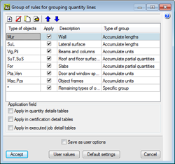
The option “Group quantity lines” (Show > Configuration), complements this new development to group quantity lines coming from the extraction from the Revit model. If the option “Apply in quantity details tables” is not activated in the dialogue box that opens (Group of rules for grouping quantity lines), the quantity details lines will not be displayed as grouped, even though the criteria for them to be grouped has been established. This dialogue allows users to define rules to group details lines of quantity tables (on-screen, when printing or when exporting). Grouping of quantity details lines is applied to those imported from CAD/BIM files, BC3 files and those introduced by users.
Price structure selection in the “Decomposition in unit items” option
Users can view simultaneously or separately, the decomposition, in unit items, of the Budget, Study and Sales price structures.
Return to the 2017 version download area
Tel. USA (+1) 202 569 8902 // UK (+44) 20 3608 1448 // Spain (+34) 965 922 550 - Fax (+34) 965 124 950