
![]()
- IFC Builder
- AcoubatBIM by CYPE
- CYPEFIRE Sprinklers
- CYPECAD MEP, CYPETHERM HE Plus, CYPETHERM RECS Plus and CYPETHERM EPlus
- CYPETHERM HE Plus, CYPETHERM RECS Plus and CYPETHERM EPlus
- CYPETHERM HVAC
- Return to the 2017 version download area
IFC Builder
Program interface improvements
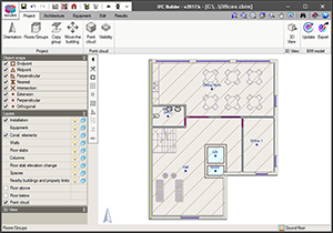
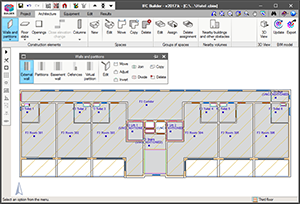
As of the 2017.k version, the interface of IFC Builder has been improved. This new feature consists of an aesthetic and functional improvement, where the toolbar of the program has been adapted to the new screen resolutions.
This new format favours the “usability” of the program due to its options being organised in categories (project, architecture, equipment, edit and results) which aids with the workflow and favours productivity in the modelling process.
As occurred in the previous version (2017.j) with the interfaces of CYPETHERM HVAC and StruBIM Foundations, the menu options that contain several tools, display their options in floating menus. For IFC Builder, these menus contain two viewing options, which are selected alternately by clicking on the icon  located to the left of their heading:
- Horizontal with large icons and description texts of the tools
- Vertical with small icons and description texts of the tools
The floating menus can be pinned to the screen by selecting the icon  located to the right of the heading (
 Pinned, unpinned), and this way do not disappear when another tool group is selected or the program is re-entered. They can also be adhered to the sides of the working space to become toolbars (see the Floating toolbars section of the new features of the 2017.j version).
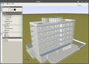
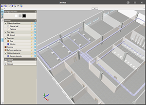
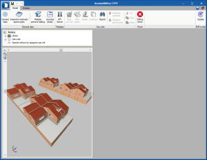
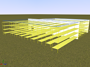
New colours and textures of the 3D view
The colours and textures of the 3D view have been redefined and adapted to the specification detail of the geometric model.
AcoubatBIM by CYPE
Façade and roof claddings
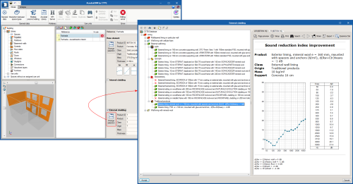
As of the 2017.k version, AcoubatBIM by CYPE allows users to introduce external claddings for the roof and façade types, as was done in previous versions for partitions and floor slabs. Thanks to this implementation, ETICS insulation systems can now be introduced in the construction solutions used in the building.
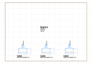
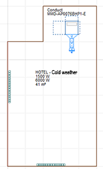
New project examples
The following examples have been added:
- Education room (English)
- Detached houses (English)
- Salle de classe (French)
- Ayuntamiento (Spanish)
- Restaurante (Spanish)
- Hotel (English)
- Duplex (English)
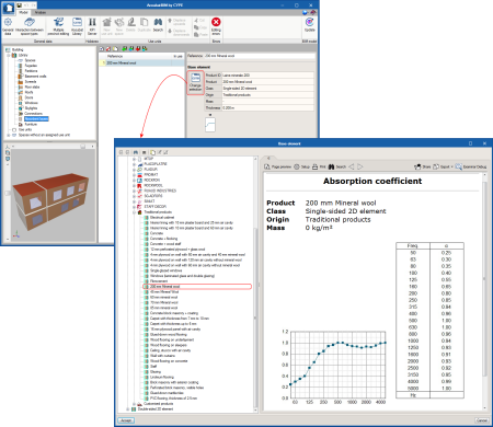
Absorbent layers
The group “Absorbent layers” has been added to the program library. This way, users can include 2D absorption elements in the project model. These, as occurs with furniture, are not taken into account in the sound insulation calculations and only affect the prediction of the reverberation level inside the space in which they are installed.
Since the types of absorbent layers are characterised by their sound absorption coefficient (α), they must be associated with the internal or external side of the partition.
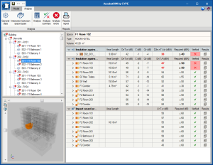
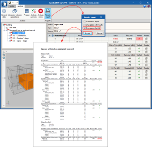
Project results report
A summary document has been created containing the results of the global acoustic indices obtained for each space, together with the limit values established by users. Similarly, users can configure the elements to be displayed and only show spaces that do not meet all the requirements or values obtained for each separator or connection.
CYPEFIRE Sprinklers
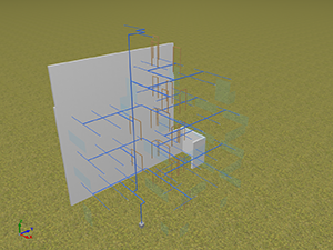
3D geometry. Risers
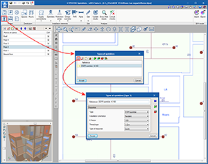
As of the 2017.k version of CYPEFIRE Sprinklers, risers can be used as vertical connections between pipes of different floors.
For this initial implementation, it is only possible to use risers if users link their project to a BIM model (even if the connection with the model is not maintained and only its 3D geometry is conserved). This feature will be further developed in future versions, where it will be possible to introduce risers without requiring the connection with the BIM model and users will have a palette of options regarding their definition, such as being able to introduce sloped risers.
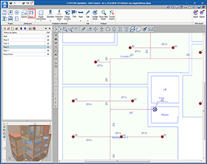
Risers are located in the “Pipes” menu. Users must define the reference, material and size to be used. Once the riser has been introduced on the floor plan, it will be displayed in a lighter colour (transparent layer) on the other floors. The riser has to be introduced on all the floor plans where it will be connected to horizontal pipes. When it is introduced on other floors, it is displayed in a darker colour (the same way as occurs on the floor plan where it was first introduced).
Risers are also included in the reports and are clearly identified in the nodes lists with the reference: “Riser node”.
ESFR – Sprinklers
The 2017.k version includes a new type of sprinkler: ESFR (Early Suppression Fast Response).
The main properties of this sprinkler are its fast response and its discharge factor, K, which is greater than 11.2 gpm/psi1/2 (160 lpm/bar1/2). It is known for its great capacity to suppress fire and its use in high risk zones. These sprinklers are usually used to avoid having to include In-Rack sprinklers in the installations.
Racks
The 2017.k version of CYPEFIRE Sprinklers includes racks, an important element when designing a sprinkler system.
The racks pose a challenge for designers because the type of installation to be executed depends on their geometry and what they store.
In this version, users define the height of the racks and their geometry on plan, which will then be used by the program to carry out the necessary checks on the ESFR sprinklers. More information on the racks can be implemented in future versions, such as the type of material that is stored (Class I to IV, rubber tyres, etc.) the geometry of the rack (solid shelving, palletized racks, portable racks, etc.) and the introduction of sprinklers at each level of the rack (In-Rack sprinklers).
Edit Menu
As occurs in CYPEFIRE CTE, the Edit section of the bar menu displays its elements in a floating menu which can be viewed in three different ways:
- Horizontal with large icons
- Vertical with large icons
- Vertical with small icons and description texts of the tools
The floating menu can be pinned on screen so that the options remain visible when others are being used. It can also be placed to the side of the workspace so it resembles a toolbar.
This type of menu is the same as that which was implemented in the 2017.j version for CYPETHERM HVAC and StruBIM foundations (see the Floating tools section of the new features of the 2017.j version) and in this version (2017.k) for IFC Builder.
Additionally, the following tools have been added to this menu for CYPEFIRE Sprinklers:
 Assign
This tool, already known in other programs, allows users to quickly assign the same properties to different sprinklers or pipes. Once the option has been selected, users click on the element to which its properties are to be copied and an editing panel appears with its data. After the panel has been accepted (in which users can modify data), another element or other elements can be selected (one by one or using a selection window). Once all the elements to which the properties of the panel are to be copied have been selected, a right click on the mouse button confirms the action to copy the properties. Measure lengths on plan
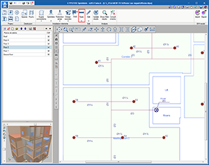
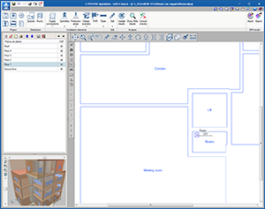
Allows users to quickly make on-screen measurements. Move tag
When an installation consists of a complicated arrangement of pipes, it may be difficult to view references, diameters and nodes clearly. Now, these tags can be displaced by users to obtain clear and more effective plans. Show/hide tag
For the same reason as indicated for the option above, there may be irrelevant information hindering a correct view of the drawing, hence users can also show or hide tags. Tag line
If, having displaced a tag, it is difficult to see to which element it refers, it is possible to draw an auxiliary line using this tool which links the tag directly to the reference element. Insert text
Allows users to introduce text on the interface to provide further information on the installation. This text can be printed in the drawings.
CYPECAD MEP, CYPETHERM HE Plus, CYPETHERM RECS Plus and CYPETHERM EPlus
EnergyPlus analysis engine update to version 8.7
The EnergyPlusTM analysis engine has been updated in the 2017.k version in all CYPE programs that use it: CYPECAD MEP, CYPETHERM HE Plus, CYPETHERM EPlus and CYPETHERM RECS Plus. This way, all CYPE programs will now use the latest available version of the analysis motor of the US Department of Energy (DOE); version 8.7, published on 31st March 2017.
CYPETHERM HE Plus, CYPETHERM RECS Plus and CYPETHERM EPlus
Toshiba variable refrigerant flow systems
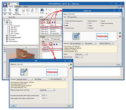
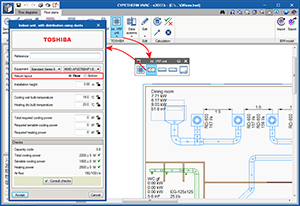
Toshiba VRF systems have been implemented in the catalogue selection of variable refrigerant flow systems. As well as being able to define the properties of a “generic” VRF system, as up to now, users can choose amongst the Toshiba models that are completely defined in the program.
In the Terminal unit window (see image), when the Variable refrigerant flow (VRF) option is selected, users can choose indoor Toshiba units by type and model. Their main catalogue properties are displayed.
Similarly, outdoor units can be found in the Variable refrigerant flow (VRF) tab of the Systems window.
CYPETHERM HVAC
Connection of indoor VRF units with duct distribution
Air discharge
When a discharge grille is introduced (Ducts > Straight duct), a snap point appears on the indoor VRF units with duct distributions on the current floor.
This point is the starting point of the discharge duct that joins the indoor unit with the rooms it provides air to. This way, the program automatically distributes the loads of those rooms and the air flow moved by the unit, between the grilles and diffusers of the discharge duct.
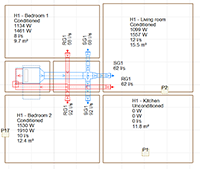
- Load distribution
When the project is analysed, the thermal loads of the rooms connected to the indoor unit with the discharge grille are transferred to the indoor machine. The program takes into account the following configurations:- Several machines providing air to the same room
The program will distribute the load equally for each machine - One machine providing air to several rooms
The load assigned to the machine will be the sum of all the rooms - There is another system in the room
If another system exists in the room to which the VRF unit provides air, e.g. a radiator, the load assigned to the machine will be the remaining load (the room load minus the radiator load), as long as the “Simultaneous” option has been selected in “General settings > Distribution of the thermal load of the precincts amongst the systems”.
- Several machines providing air to the same room
- Air flow distribution
When the air flow that is moved by the machine is calculated, it is shared amongst the grilles and diffusors of the discharge duct. The program takes different configurations into account:- One machine that provides air to several diffusors and grilles in the room
In this case, the program will divide the flow between them. If users set the flow of a grille or diffuser at a specific value, the remaining flow moved by the machine will be shared amongst the grilles and diffusors that do not have a set flow value. - One machine that provides air to several rooms
This is the usual case in dwellings. The discharge flow is shared amongst the discharge duct grilles depending on the cooling load of each room.
- One machine that provides air to several diffusors and grilles in the room
Air return
The configuration of the return position is defined directly in the panel of the indoor unit. There are two possible return positions:
- Rear
In this case a return duct network will have to be provided. - Bottom
It will be placed opening to a grille in the false ceiling without a return duct network.
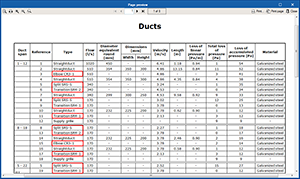
ASHRAE reference for duct fittings
Fittings (elbows, transitions and splits) appear in the duct lists (“Type” column) with their ASHRAE reference. This data allows for the element to be identified more clearly.
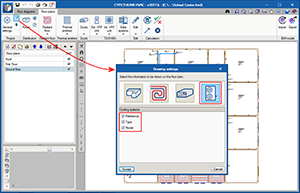
Information on Toshiba Estia and VRF systems on floor plans
The “Cooling systems” button has been included in the “Drawing settings” dialogue box, which allows users to activate the reference, type and model of the indoor and outdoor VRF system units and TOSHIBA Estia units, to then display this information on floor plans.
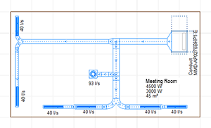
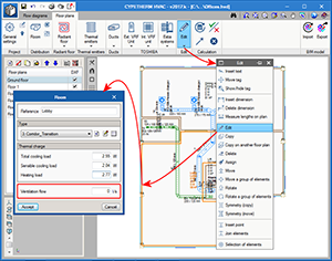
Ventilation flow rates
The 2017.k version includes the “Ventilation flow” for each room. As occurs with loads, this data can come from the BIM connection with CYPETHERM LOADS or defined manually in the program by users.
Radiant floor
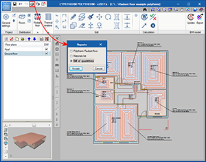
Bill of quantities for Polytherm products
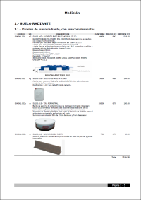
The 2017.k version of CYPETHERM HVAC and CYPETHERM Polytherm contain the bill of quantities which includes the Polytherm products used in the design of the installation. This way, as well as the program providing a complete report of the results of the installation designed with Polytherm, the programs incorporate a detailed bill of quantities of the Polytherm radiant floor, with images, descriptions, prices and quantities of all the products.
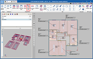
Radiant floor path editing tools
As of the 2017.k version, CYPETHERM HVAC and CYPETHERM Polytherm incorporate a new tool to edit radiant floor circuits, which users can use to modify the paths that are generated automatically by the program.
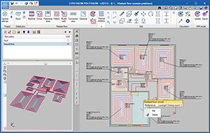
Contextual menu of the installation elements
When the right mouse button is pressed when the cursor is positioned over an element of the installation, or over the limits of a room, a contextual menu appears containing options to edit or delete the selected element, or consult results when applicable (e.g. of ducts).
Return to the 2017 version download area
Tel. USA (+1) 202 569 8902 // UK (+44) 20 3608 1448 // Spain (+34) 965 922 550 - Fax (+34) 965 124 950